All my boards come preflashed with the latest web server. Normally you do not have to flash the firmware again. Updates are very rare. But if you need to flash it, here is a guide. You will need:
NodeMCU PyFlasher or esptool.py (NodeMCU PyFlaser got a nice GUI ;) )
Micro USB Cable
DuetWifiServer.bin (not the -duet version)
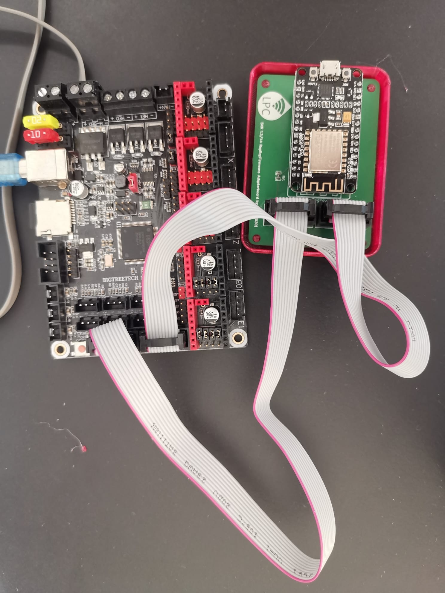
1. Disconnect EXP1 and EXP2 of the SKR RFF Adapterboard.
2. Now plug the Micro USB Cable into the ESP8266
4. Now open NodeMCU PyFlasher or the terminal for using esptool.py
5. Choose the Serial Port, the DuetWifiServer.bin, the Baudrate,Flashmode (DIO for my ESP Modul) and do NOT erase the Flash. If you are using esptool.py use this guide:

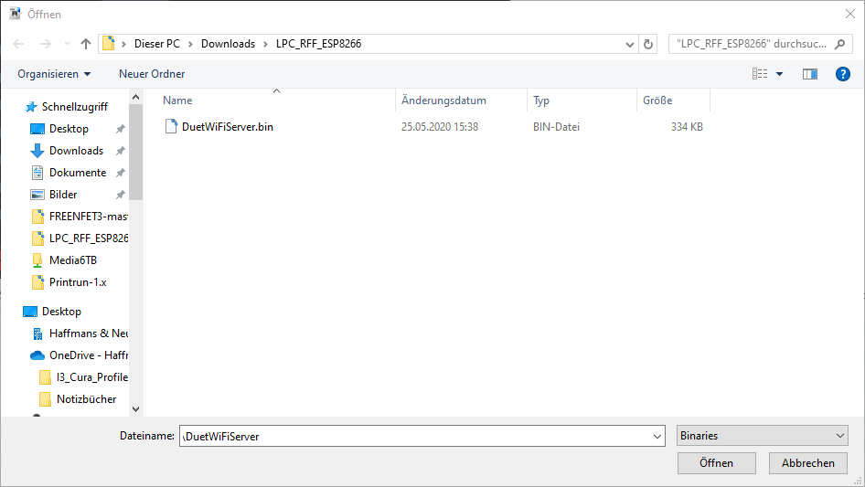
6. Now press "Flash NodeMCU". It will say

7. Now press and hold the FLASH Button on the ESP. The flashing process will now start:

8. After the flashing is complete, you can disconnect the micro USB cable. Now you can plug EXP1 and EXP2 in and start the printer!
As always here is a little video:
https://www.youtube.com/watch?v=62HPfa_pfys
Due to the fact that the EXP1 and EXP2 Ports are used by the Wi-Fi Adapter it is not possible to connect a standard LCD to the SKR.
A Display is not needed to use the RepRapFirmware. You can start, configure etc everything via the web interface.
The display is an add-on and not mandatory! But if you want to have one, you have two options.
1.Using a TFT35 from Bigtreetech with a modified firmware
2.Using a PanelDue
I will show you how you can connect a PanelDue to the SKR Board. These are available quite cheap from aliexpress! Only drawback is, that you cannot print from SD card slot of the display!
- Updating the firmware of the PanelDue. This ist pretty easy. Click here
- Using the 4 Pin cable to connect to the SKR.
On the SKR you have 4 pins labeled TFT. On the underside of the board the pins are labeled with RST R0 T0 G 5V. We need ever pin except the RST.
.jpeg)
On the PanelDue the 4 Pin Connector is labeled TXD RXD GND +5V
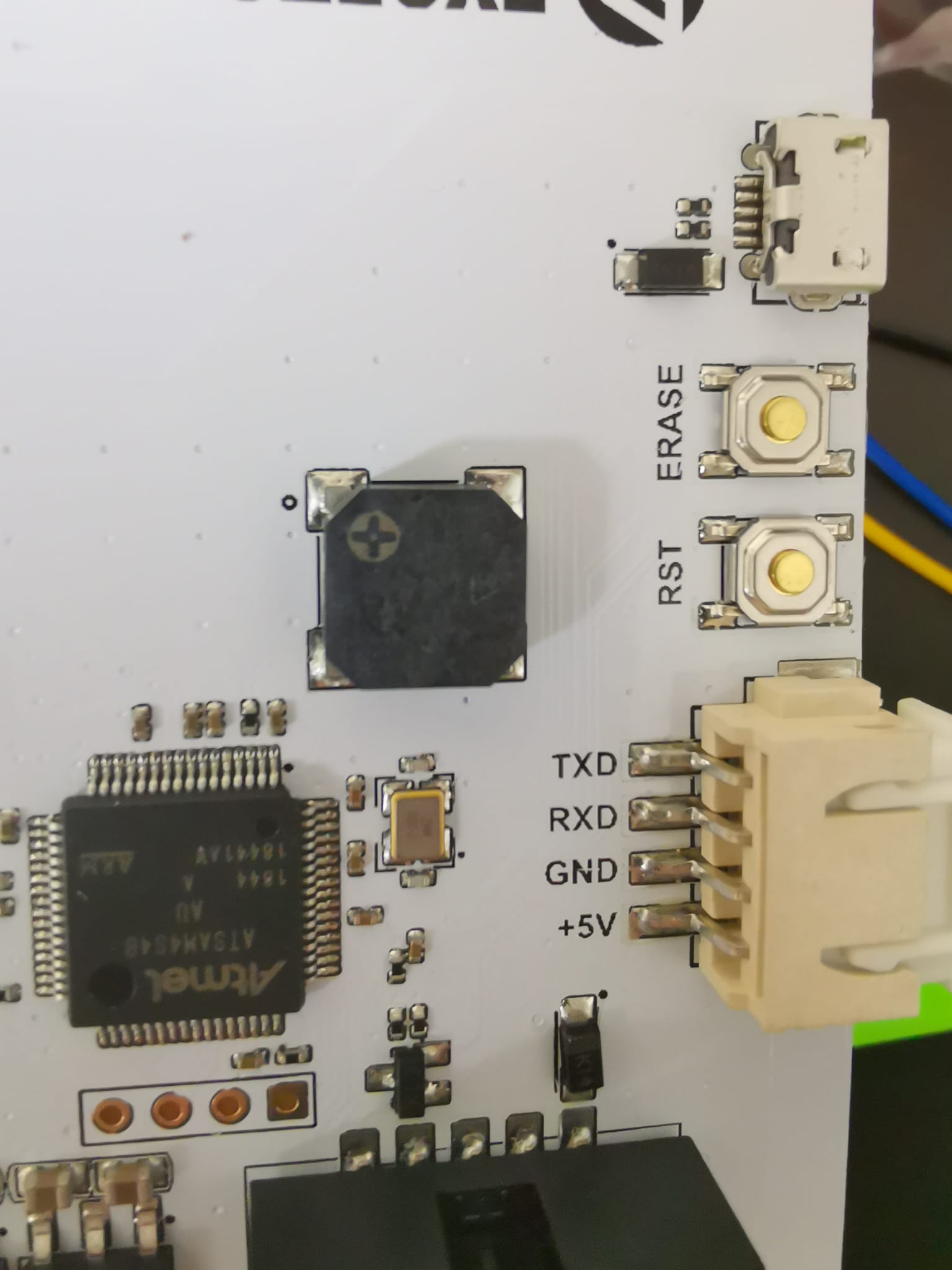
Now you have to be careful You have to connect the wires like this. (left Paneldue right SKR). I had to change the pins of the SKR side. For this you can press the little metal tab down and pull the wire out.
GND->G
+5V->5V
RXD->R0
TXD->T0
Now we have to add a line in config.g
M575 P1 S1 B57600
Save and reset the Board.
Now the display should work. If not got to Setup and change the baudrate to 57600 baud.
All SMD parts are solderd on by the factory! So no sketchy soldering by me ;)

The price seems quite high for such a simple board. But I can explain this.
Due to the COVID19 crisis I have to buy most of the parts directly in Germany. I also solder the most parts myself and test EVERY board with my SKR! I also preflash the 8266 chip! In the end I do not make any money with this. My goal is to help the community out.
After some days a package arrived at my apartment, the RFF LPC boards are here! Hurrraaay!
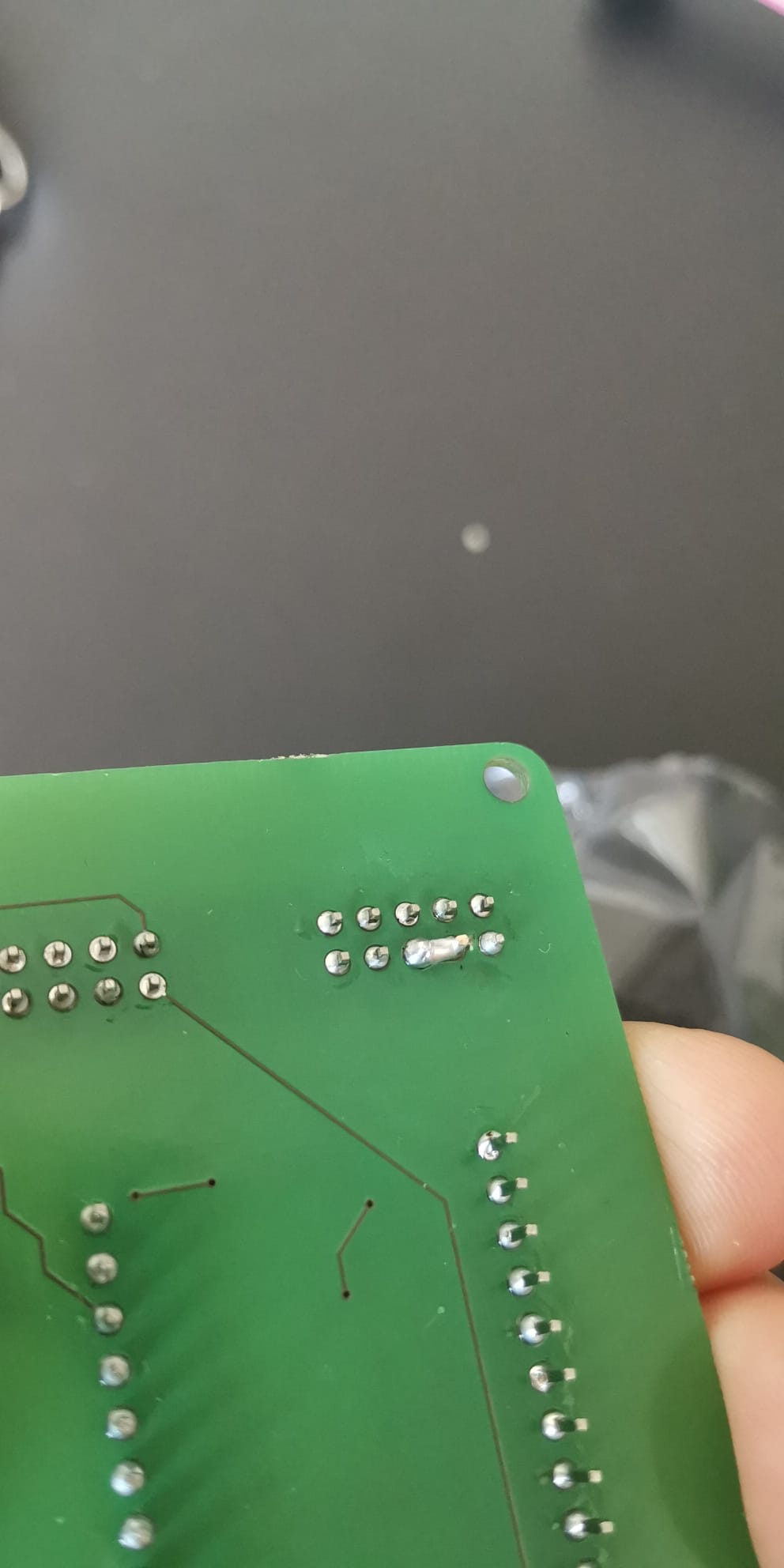
So the first step is to solder the tiny 0805 resistors by hand. I have never done that before! So I watched some videos and it looks like I can do it! Some frustrating minutes later I finished with the soldering. Was not that hard but please do not judge my solder joints ;)
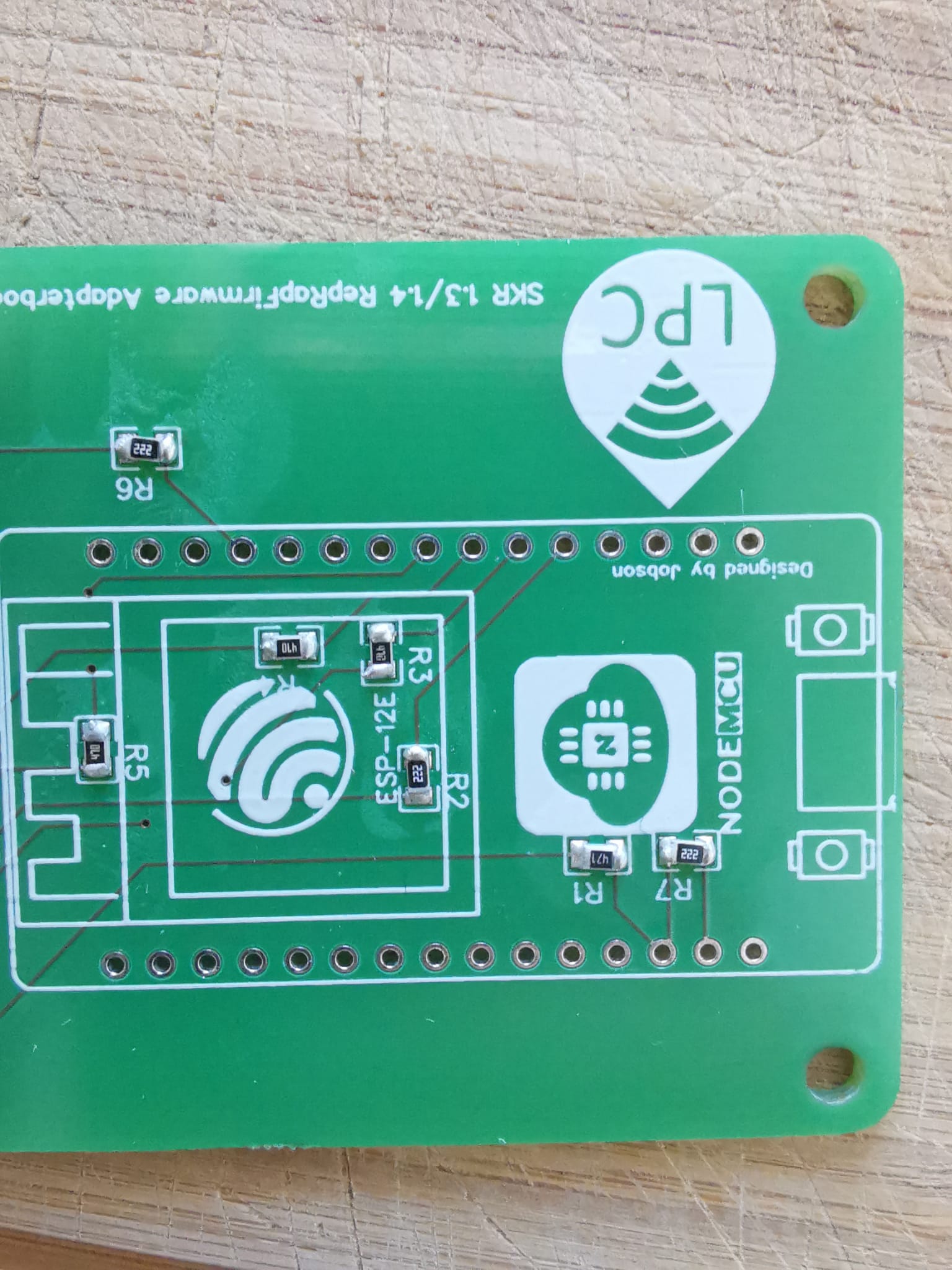
I measure every connection with my multimeter and everything seems ok. Nice! Now I go on with soldering the IDC connectors and the ESP8266 on it. Some minutes later. What the heck. My 8266 V3 has wider pins that the footprint in EasyEDA. I already knew that the V3 is wider than the V2. That's why I searched for the V3 in the library. But the footprint was wrong.... But lucky me! I have some V2 lying around too! Some minutes later the board is ready for testing.
But it did not work. The board keeps resetting itself. After I measured every trace, I saw the mistake. I connected the RESET pin of the ESP to the RESET Pin of the SKR and not to the 1.31 pin... Idiot!
The fix for that was easy! The RESET Pin and the 1.31 are neighbors! So one solder joint and one cut pin later the board works!
I quickly updated my schematic!
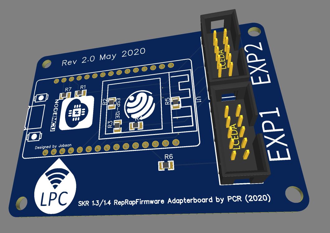
In my last post I talked about the RFF on LPC Project. For making things easier I wanted to make a PCB which I can connect via two 10 pin IDC cables. This are the same which are used for the normal LCDs! For making the PCB I used EasyEDA.
This is a web application which is an all-in-one solution. You can make the schematic, the PCB layout and the BOM list all in one software. Also, the ordering via JLCPCB is integrated. As I am no electronic engineer, I am not super familiar with PCB design. But i can do the basics! So first step was to make the schematic. This is very simple and looks like that:

After that you have to place the components and route the traces! Very easy too! After some work it looks like that:


The next step is to order the PCB on JLCPCB. The process is very simple. If you want to learn more there are a ton of videos on YouTube!
So now I have to wait till the PCBs arrive at my door from China....
Some nights ago i saw an intresting repo on github https://github.com/gloomyandy/RepRapFirmware.
gloomyandy and sdavi are porting the RepRapFirmware (RFF) to LPC176x boards. This means you can run them on a SKR 1.3 etc.
Normally RepRapFirmware is only used on Duet boards (Duet2WIFI,DuetMaestro). In my opinion the RRF is superior to Marlin. Some key points
No more compiling of the firmware. EVERY Setting you can change via a webinterface
The 3D printer is completly controled by the DuetWebControl (DWC) web interface. No need to attach a raspberry with octoprint or another control software. File Upload and everthing is handeld by DWC
Easy firmware update via DWC. Easy backup too.
The cheapest genuine duet board available in Germany cost about 100€. If you are ok with buying a clone* they are available for half the price (50€) on aliexpress. So if you are thinking about going the RFF route i would buy a duet clone directly. The only drawback is that you have to change the connectors on your typical 3D printer (Creality, Anycubic etc,) from JST XH to MOLEX KK. You can use this kit https://www.amazon.de/KF2510-Kit-KF2510-Housing-Adapter-Connector/dp/B01N4O7PP2/ and you need a crimping plier too https://www.amazon.de/Dupont-Crimpwerkzeug-professionellem-Ratschenmechanismus-isoliert/dp/B01A0SAQ3W/.
But if you have a LPC176x board lying around or already running with marlin you can now use RFF too! If your board has a RJ45 port its easy as flashing a firmware.bin. But most of the boards doesn't have one. The SKR boards from Bigtreetech have no network connection at all! It's possible to run RFF without a network connection but i would not recommend it. You will lose a lot of features. So how we add WiFi to the SKR boards? Quite Easy. You only need a ESP8266/ESP-12F/Wemos D1 board/chip and some resistors + cables. The complete guide is here : https://github.com/gloomyandy/RepRapFirmware/wiki/SKR-Wifi.
After some quick solderin my the first prototype of my board was ready.

And everthing works flawless! But to make the connecting easier i gonna make my own PCB.